Filter 4 and 5 now have re-circulation systems installed. Both of these filters had failed miserably in April/May of this year due to lack of water throughtput, and excessive organic debris present in the input water. Since the re-circulation systems have been installed and running for 2 months, the water in both filter systems has improved tremendously. The foul odor is gone, and the water is clear again. The details follow.
There have been 5 options for re-circulating water used here. Totally manual, an electronic timer, a modified ball valve, a modified standard hose bib, and a drip irrigation timer. All five work. The modified standard hose bib was the most difficult to set up and the least professional – it is not shown, even though it does work.
The manual method (adding water from a bucket filled by a hand operated pitcher pump) and the electronic timer will work with a non-pressurized system. The manual method is the most time consuming and requires daily attention.
The electronic timer switch is the Amico DC 12V Digital LCD Power Programmable Timer Time Switch Relay 16A sku 40037612 This timer will handle 16 amps. We are also now testing out a PV array set up to charge and run small dc motors of the size used in the pumps on the recirculation systems shown here. So far, a 50 watt PV array produces waaayyyy more power than is needed to keep the motors running during the summer months when there is little or no rainfall. The recirculation is not really needed in the fall, winter, or spring, so the lack of sunshine is irrelevant.
Much more info as I get time. . . . right now “I got all the freaking work I need”.

This is the ball valve. It is in use on filter 4 along with the electronic timer, for test purposes only. Either this or the electronic timer will work alone. The extended arm on the ball valve allows very fine adjustment of flow rate.The electronic timer is not needed, we are just testing it out.

This is the programmable timer. It will work with or without a pressurized system. It just turns the motor off and on at specified times. Up to 17 choices in 24 hour time period. This is in use with filter 4. So far the timer works like a charm. The "manual" button allows the water to be turned on and off anytime without disturbing the programmed times.

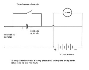
this is a schematic of the timer circuit hookup. The battery symbol represents the 12 volt power supply for the motor and the timer. The timer must have the power supply hooked up before the relay inside it will function. The capacitor is necessary to keep the relay contacts from being burned by arcing as the motor has significant inductance.

This is the schematic of the filter 4 system that uses flow regulation and flow frequency control using the electronic timer switch.


